What is JAMMA?
JAMMA stands for Japanese Arcade Machine Manufacturers Association and is the standard that the vast majority of game boards/cabinets will conform to. While this sounds like something really technical, that really couldn’t be further from the truth! All JAMMA really is, is the order that connections are made to an arcade board.
Let’s take a look at a normal JAMMA arcade board edge connector, in this case a Taito F3 motherboard.
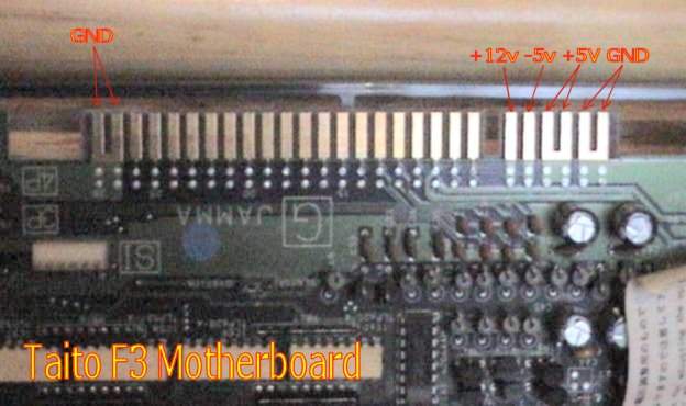
First thing I will point out seeing as this is a beginners guide, is that the side showing is the ‘parts’ side. The underside of the board is just solder and tracks/rails (the lines on a PCB that join the parts together). The easiest way to ensure that you are matching the right wires to the right pins is to take note of the tracks connecting the power. If you look at the connections for the Ground/ +5V/ -5V/ +12V you’ll notice that the tracks are considerably wider than the others. Also, the power connections that have two connections next to each other are joined together in a ‘U’ - this is not always as obvious as this example, but they will still be connected somewhere! You can use a multimeter to test for this on the continuity setting.
The other slightly wider tracks on this PCB are for the speakers, you should be able to see where each connection goes from this example…. Hopefully…
Now compare the edge connector with the pinouts… And you’ll see how straightforward this really is!
       This Video Game Pinout Data Sheet Was Typed In By James R. Twine.
                     EMail:  jtwine@jtwine.com

                     -> JAMMA Standard Connector <-

Name Of Game: N/A
Notes: Not all games will use all pins, and some kits may have extra connectors
       for more/different controls!  i.e. Street Fighter II and Ikari Warriors.


            Solder Side            |             Parts Side
   ________________________________|___________________________________
               GND             | A | 1 |             GND
   ----------------------------|---|---|-------------------------------
               GND             | B | 2 |             GND
   ----------------------------|---|---|-------------------------------
               +5              | C | 3 |             +5
   ----------------------------|---|---|-------------------------------
               +5              | D | 4 |             +5
   ----------------------------|---|---|-------------------------------
               -5              | E | 5 |             -5
   ----------------------------|---|---|-------------------------------
               +12             | F | 6 |             +12
   ----------------------------|---|---|-------------------------------
             - KEY -           | H | 7 |           - KEY -
   ----------------------------|---|---|-------------------------------
        Coin Counter # 2       | J | 8 |      Coin Counter # 1
   ----------------------------|---|---|-------------------------------
       Lock Out Coil # 2       | K | 9 |     Lock Out Coin # 2
   ----------------------------|---|---|-------------------------------
           Speaker (-)         | L | 10|         Speaker (+)
   ----------------------------|---|---|-------------------------------
                               | M | 11|
   ----------------------------|---|---|-------------------------------
          Video Green          | N | 12|        Video Red
   ----------------------------|---|---|-------------------------------
          Video Sync           | P | 13|        Video Blue
   ----------------------------|---|---|-------------------------------
         Service Switch        | R | 14|        Video GND
   ----------------------------|---|---|-------------------------------
           Tilt Switch         | S | 15|          Test Switch
   ----------------------------|---|---|-------------------------------
         Coin Switch # 2       | T | 16|        Coin Switch # 1
   ----------------------------|---|---|-------------------------------
           2P  Start           | U | 17|          1P  Start
   ----------------------------|---|---|-------------------------------
           2P  Up              | V | 18|          1P  Up
   ----------------------------|---|---|-------------------------------
           2P  Down            | W | 19|          1P  Down
   ----------------------------|---|---|-------------------------------
           2P  Left            | X | 20|          1P  Left
   ----------------------------|---|---|-------------------------------
           2P  Right           | Y | 21|          1P  Right
   ----------------------------|---|---|-------------------------------
           2P  Button 1        | Z | 22|          1P  Button 1
   ----------------------------|---|---|-------------------------------
           2P  Button 2        | a | 23|          1P  Button 2
   ----------------------------|---|---|-------------------------------
           2P  Button 3        | b | 24|          1P  Button 3
   ----------------------------|---|---|-------------------------------
                               | c | 25|
   ----------------------------|---|---|-------------------------------
                               | d | 26|
   ----------------------------|---|---|-------------------------------
               GND             | e | 27|             GND
   ----------------------------|---|---|-------------------------------
               GND             | f | 28|             GND
   --------------------------------------------------------------------
So, let’s look back over this short lesson… When we talk about a JAMMA connector we are referring to a wiring loom that provides power to the necessary pins on the arcade board. It also connects the Red/Green/Blue/Sync/Video Ground for the video signal, the speaker output and all the player inputs - its just a standard 28 way double sided edge connector (0.156" pitch) with a load of wire, but connected in a specific order.
There’s no need to make a supergun as such, you really can just join the dots and have a fully operational arcade game as long as you have a power supply, monitor/TV and controls. But of course, building a supergun makes everything nice and neat - after all you wouldn’t have the innards of your Sony Playstation on display would you!?!!
One thing I will point out here but is covered in greater detail on a later page (Can I play games that aren’t JAMMA?) is that nearly all non-JAMMA arcade games use the same voltages and inputs/outputs. Therefore, they are still usable in your machine, but an adaptor needs to be built to connect the necessary pins to their correct locations. NOTE!!! That reads NEARLY all, there are some that use obscure voltages, negative video signals or a different type of monitor…