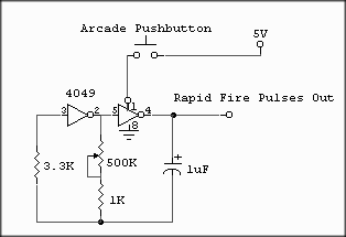
Autofire Circuit
This circuit converts a single held switch press into a steady stream of output switch presses with an adjustable pulse rate. By adjusting the rate of the output pulses, an arcade button that is being held down will constantly re-trigger the output at a rate variable between once every 1 or 2 seconds, to many times a second, much faster than a person could normally press the button. This wide range of pulse durations, from too-slow to too-fast, allows for any reasonable configuration desired.
The arcade switch in the circuit below is simply a power switch for the oscillator. When you push the button, you’re connecting power to the oscillator and it begins pulsing at the rate set by the variable resistor. When you release the switch, you turn the power off and no button presses are registered.

This type of oscillator is called a relaxation oscillator. There are different ways to make a relaxation oscillator, using Op Amps, transistors, etc. They have that name for a reason based on the way they operate.
The resistor and capacitor values were determined completely experimentally, although there is a formula to calculate the frequency. On a simple circuit like this, just building it and connecting an LED on the output to visually tune it is more reliable than assuming the math is done right. The interesting thing is the 1k resistor in series with the 500k variable resistor (POTentiometer). The original circuit just has a single resistor in that area of the circuit where the pot and 1k resistor are. With just a pot in the circuit and no 1k resistor, the resistance can be set from 0 to 500k. The lower the resistance, the faster the flash rate. The higher the resistance, the slower the flash rate. When the pot’s dial is set on the extreme end that provides a resistance of zero, the oscillator does not behave as we would prefer. By experimentally turning the dial until the oscillator was flashing the test LED at a reasonably fast rate, without going unstable, the resistance of that POT setting was measured. This value is the minimum resistance that should ever be present in that part of the circuit. To put a restriction on the pot and keep it from going below that minimum resistance (because it can be adjusted right down to 0), the measured minimum desired pot setting of around 1k suggests that we should put a 1k series resistor with the pot. This way, when the pot is set at 0, there is still at least 1k of resistance in that area, and the oscillator will send fast pulses still. When the pot is adjusted the other way to slow down the pulses, the 1k just helps slow it down even more within that dial turning range. Compared to the 500k pot, the 1k resistor doesn’t add much extra significant resistance, so it works just fine.